


Wireless vibration sensors are an enabling technology driving the biggest improvements in asset reliability since the advent of route-based vibration monitoring. These sensors are one of the most important components of predictive maintenance programs because their measurements are foundational to directing corrective maintenance tasks and ultimately reduce plant downtime.
Excitement over this new opportunity has flooded the predictive maintenance market with inexperienced companies and poorly designed sensors, many of which are error-prone. This problem can be hidden by clever analytics and misrepresented sensor accuracy specifications. Unfortunately, the limited scope and duration of pilots often don’t expose this problem as will become evident in this article. This article enables end-users to avoid error-prone sensors by arming them a simple way to estimate the expected error using several key physical sensor characteristics, which are easily found by a non-expert.
The magnitude of this problem is significant because experimental testing shows that peak error in transverse (lateral to the sensor) vibration ranges from 60% to 410% for common sensor designs.

Sensor Design and Accuracy
For more than 60 years, experts in vibration measurement have refined accelerometer designs to improve their accuracy. The resulting wired accelerometer products have a highly compact form factor and stable mount to the machine. In contrast, accelerometers built by many incumbent wireless sensor companies have an unstable form factor (high center of mass and narrow base). This article shows that however challenging it is to design a compact wireless vibration sensor, it is not challenging to intuitively judge a sensor’s measurement accuracy.
If machine vibration were only perpendicular to the sensor mounting surface and the center of mass of the sensor aligned with the mounting point, most wireless sensors would perform reasonably well. However, vibration, on average, is often relatively consistent across three dimensions. Most importantly, vibration parallel or tangential to the mounting surface (lateral or transverse to the sensor) can cause the sensor to sway.
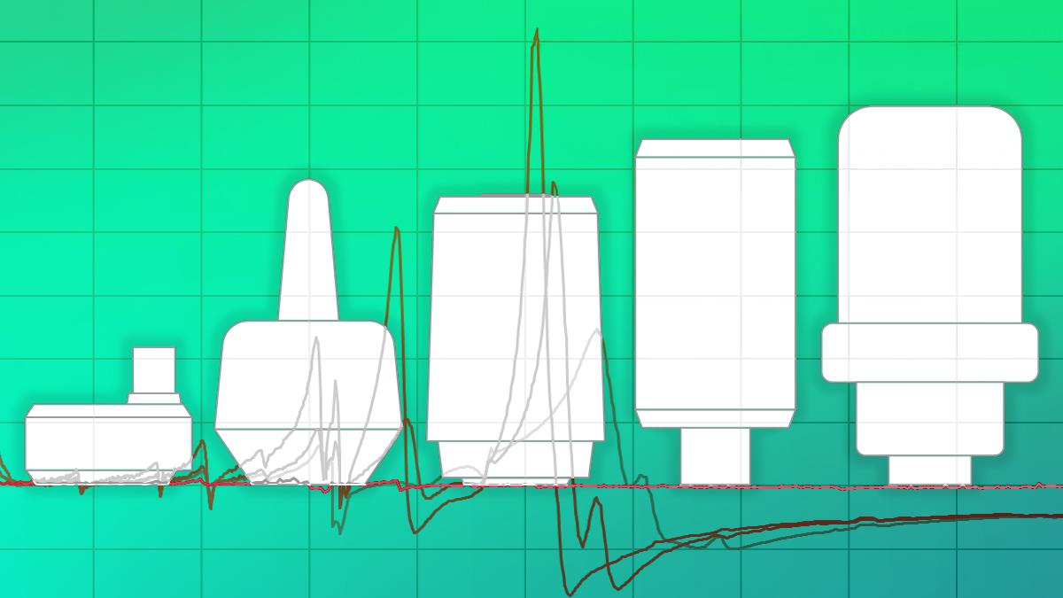
Three key parameters can be used to express a sensor’s expected sway: 1) total sensor mass, 2) height of center of mass, and 3) width (diameter) of the base in contact with the machine.

To show how these key parameters influence wireless sensor measurement error, a test was completed in a controlled laboratory environment. A representative sensor was built that matches the height, weight, accelerometer location, and mount of common wireless vibration sensors. The sensor was stud-mounted on a shaker table and vibrated horizontally or laterally.

The ratio of the measured input acceleration (lateral) relative to the lateral acceleration measured in the representative sensor was computed. Three different representative sensor configurations were tested and compared to the KCF VSN3. The first configuration includes the base and outer shell but no added mass. The second and third have a 33g mass (similar to the weight of a TL-4920 battery found in some wireless sensors).
The frequency responses of each of these variants are shown in the plot below. A value of 1.0 means the acceleration measured in the representative sensor matches the movement of the shaker (or machine). A value of 0.5 means the representative sensor only reported half the amplitude level of the machine. A value of 2 means the sensor over-reported the vibration of the machine by a factor of 2.

Best practices in sensor design seek to ensure that the sensor is rigid and has a low enough center of mass that its “natural” frequencies lie above the measurement range. This is a design challenge because many wireless sensors have large batteries, antennas, and circuits that tend to move the natural frequencies of the sensor into the measurement range of the accelerometer.
KCF has minimized this problem using its patented wireless solution called DARTwirelessTM that reduces power consumption by as much as 8X [2,3], which allows the battery to be smaller, lighter, and located lower in the sensor housing.
Estimating Sensor Accuracy
A simple metric called the “Instability Index” can be used to assess the sensor stability and error potential. It is defined as the sensor's total mass multiplied by the height of the center of mass divided by the base width. The width in this case is usually just the diameter of the contact patch between the sensor and the machine. The height of the center of mass can be estimated by laying the sensor horizontally on a pen and balancing the sensor. The distance between the balance point and the mounting surface corresponds to the center of mass height.

The measured error and Instability Index for the three wireless sensor configurations, along with that of KCF’s VSN3, are shown in the table below. An industry benchmark for high stability, the wired Wilcoxon 993B-7 sensor, is also included in the table as a gold standard for an ideal sensor design.

In the plot below, the Instability Index is plotted versus the peak error measured in the lab test.

Notice that sensor error increases with the Instability Index. However, this relationship is not linear. There appears to be a point where errors become very small for a given Instability Index. This is likely because the natural frequencies of a sensor are outside the measurement range.
Comparing Sensors in the Predictive Maintenance Market
 The above test results can be used to estimate error for various other wireless sensors by calculating their Instability Index and then mapping the Index to experimentally measured error of the representative sensor. The corresponding error is projected to be 60% to 410% for the sensor designs considered. These values are likely to underestimate error because they assume the sensor is mounted on a perfectly rigid smooth surface.
 How Error Impacts Fault Diagnosis
A peak error of 410%, (estimated for one of the sensors) is an important result that should be used when selecting a sensor. However, it is worth noting that the peak error won’t be evident in every measurement point that the sensor records. The error will only be evident at times when the key frequencies of interest (fault frequencies) for the machine overlap with the regions with high error.
This problem is compounded by the fact that many predictive maintenance software takes a baseline reading for the asset and use deviation from that baseline for diagnostics. The baseline will compensate or essentially hide the error for a period until the asset vibration changes.
The error is most problematic for accurately measuring fault signatures. This is because bearing fault frequencies like BPFI and BSF lie in the 4.5 to 20.5x RPM range and for a common 1800 RPM motor this corresponds to a frequency range of 135 Hz to 615 Hz, which directly overlaps with the peak error frequencies.
An example is shown below where error of a common wireless sensor (Instability Index of 445) is superimposed on actual vibration data from a water treatment pump in a steel mill. In this case, the water pump was cavitating, which excited a broadband increase in the noise floor. The representative sensor error amplified certain regions of the broadband noise which created false peaks in the vibration spectrum at around 360 Hz and 500 Hz. The highest false peak (500 Hz) falls within a frequency range where the bearing fault frequency BPFI is expected to lie. A second false peak lies at 360 Hz which is near the range where the vane pass frequency is expected. The false peaks could easily be misinterpreted as fault indicators.

A skilled vibration analyst could determine if the peaks represent actual faults by evaluating if the fault frequency peaks move with machine speed. In any case, chasing down sensor error is time-consuming and not what a vibration analyst wants to work on.
Conclusion
Peak error of common wireless sensors in the predictive maintenance market are expected to fall between 60-410%. This magnitude of sensor error will lead to misdiagnosis and false positives. Because the error is only expressed in certain cases, it is difficult for reliability engineers to know if a fault is due to sensor error or an actual machine fault. The Instability Index described in this article helps end-users choose wireless sensor products that will provide reliable diagnostic readings.
From the Editor: This article and its images do not reference or evaluate any specific product or company, and all analysis is based on generalized or representative sensor designs. Any resemblance to commercial products is not intentional.

About the Author

Jacob Loverich is the Chief Product Officer at KCF Technologies, a company providing predictive machinery health monitoring solutions. He...
Read More